
Power continuity and energy efficiency in U.S. Data Centers
U.S. data center electricity use has roughly tripled over the past decade, and the infrastructure behind that growth is under pressure.
According to the 2024 Report on U.S. Data Center Energy Use, total U.S. data center electricity usage climbed from 58 TWh in 2014 to 176 TWh in 2023 — about 4.4% of total U.S. electricity. By 2028, it is projected to reach 325 to 580 TWh, or roughly 6.7 to 12% of national electricity. The same report attributes much of the surge to AI.
Between servers, cooling, backup power and lighting, energy costs can account for 30 to 50% of total operating expenses. At the same time, a single dropped load can trigger outage costs and SLA penalties that erode those savings, so operators have to control energy usage while still maintaining continuity.
A data center’s reliability and efficiency are decided in the same place — the switching and metering layer between the utility, generator and load — with real consequences for uptime, operating cost and carbon footprint. It pays to specify that layer as one integrated, intelligent system rather than a set of separately chosen parts.
POWER CONTINUITY AND OPTIMIZING ELECTRICAL INFRASTRUCTURE
A data center consumes 80 to 200 times more energy than a conventional commercial building, and in many facilities, energy costs represent nearly half of the operational budget. To operate properly, a facility must control temperature, maintain constant humidity and calibrate airflow, pressurization and electrical redundancy; any deviation can degrade performance or cause a costly outage. At the same time, due to tightening efficiency standards, operators must demonstrate rigorous energy management and reduce their carbon footprint.
Precise control of power distribution and cooling can help operators stabilize their expenses. Power outages, meanwhile, are among the most costly incidents in the digital industry, and a reliable electrical infrastructure reduces downtime risk, data loss and service interruptions.
Tier ratings, defined by the Uptime Institute, determine how much continuity a facility must deliver and correspond to widely cited availability figures — about 99.982% for a Tier III facility, or about 1.6 hours of downtime per year, on an N+1 architecture. A Tier IV facility delivers 99.995%, or about 26.3 minutes per year, on a 2N or 2N+1 architecture with all distribution paths simultaneously active.
Much of that downtime risk is concentrated in the switchover from utility to generator. The utility feed is the least reliable element in the path, so every critical facility pairs it with onsite generation the load can fall back to. When the utility falls out of tolerance, the UPS instantly carries the critical bus from its battery energy storage system (BESS) while the standby plant spins up. Standby diesel generators are expected to start and accept load within roughly ten seconds.
The transfer switch controller detects the loss, orchestrates the generator start, and with the transfer switch moves the load and later returns it. A single failed transfer can cost more downtime than a Tier IV facility is allowed in a year. This solution is a small part of the facility by cost and footprint, but it decides whether the redundancy engineered everywhere else actually delivers.
THE TRANSFER-SWITCHING LAYER
A transfer arrangement is made up of two parts. The first is a dedicated automatic transfer switch controller that continuously monitors sources for voltage, frequency, phase and sequence. The transfer switch controller:
• Declares a source failed against programmable thresholds and delays
• Commands the generator to start
• The transfer switch then executes the transfer once the incoming source is stable
• Re-transfers when the preferred source returns
• Lastly, the controller Reports its status upstream
Building that logic into a purpose-built controller, rather than assembling it from discrete relays, makes the behavior repeatable, tunable to the site and auditable. Higher-tier controllers add direct current sensing on all phases plus neutral, so transfer strategy can be load-aware rather than voltage-aware alone.
The second half of the transfer-switching layer is the switching device, whose reliability is characterized by mechanical and electrical endurance — i.e., the operating cycles it performs over its life — and by its ability to withstand fault current while maintaining isolation. Because the device cycles on every utility disturbance, scheduled test and re-transfer, its rated operating-cycle life is what determines how long it survives in service.
A2L REPLACEMENT REFRIGERANTS AT A GLANCE
The ASHRAE A2L classification means lower toxicity (A), flammable (2) and low burning velocity at or below 10 cm/s (L). The table below compares the leading A2L replacements against the legacy R-410A they are displacing.
ASHRAE Standard 34 classifications.
The high LFL values — typically 10 to 19 percent volume in air compared to roughly 2 percent for propane — mean that a large concentration must accumulate before a flammable mixture forms.
The high minimum ignition energy means A2L gases need a powerful source to ignite. An electrical arc from an electromechanical contactor or switch supplies more than enough energy, which is why switching components are the primary focus of A2L compliance.
LOVATO ELECTRIC SOLUTIONS FOR DATA CENTERS
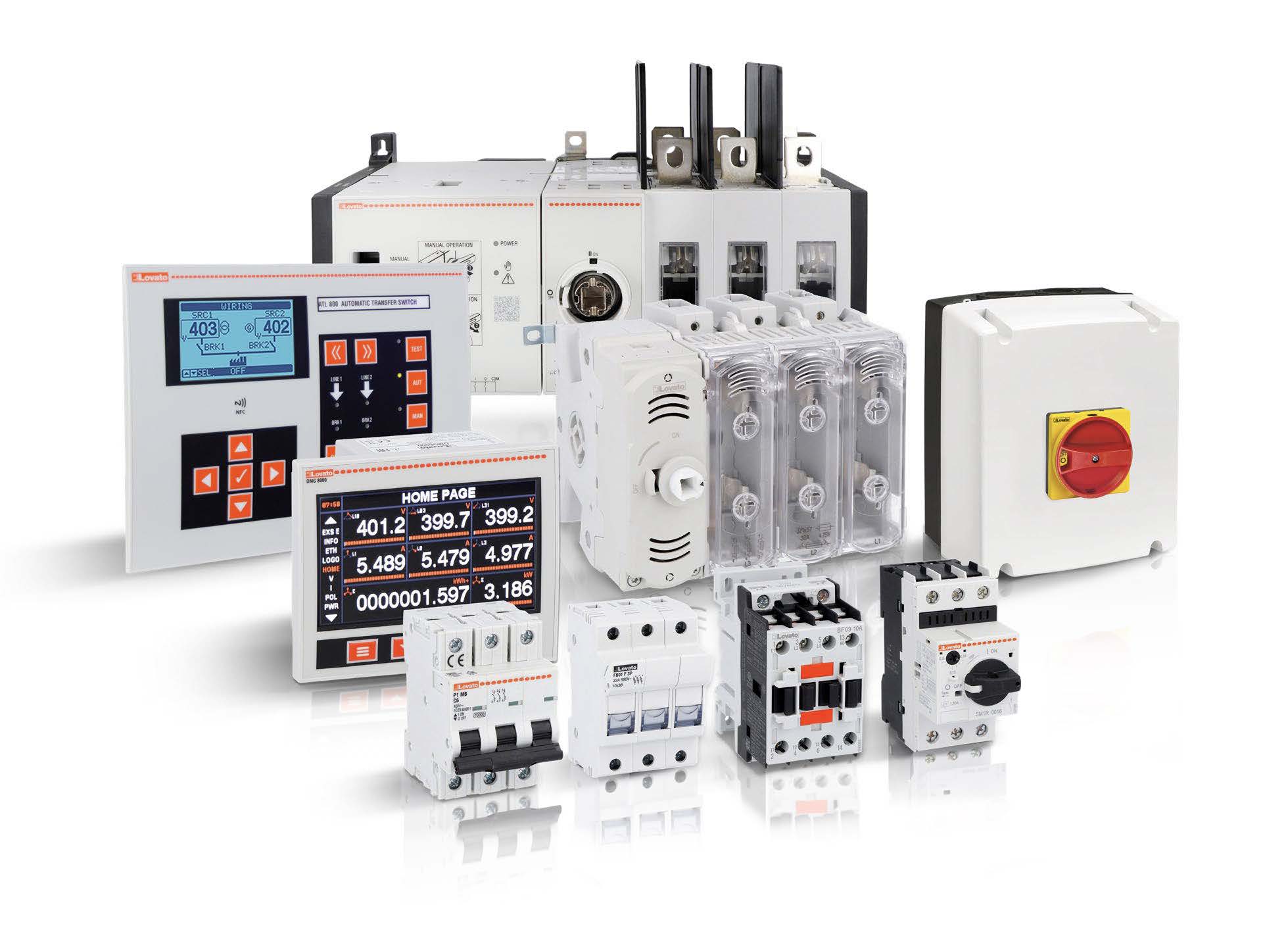
Protection and distribution. P5ME Series MCCBs (UL 489) protect against overloads and short circuits in critical installations, P1MB Series MCBs (UL 489 / UL 1077) protect secondary circuits and GA / GL disconnect switches provide safe isolation. The GA range spans 16–125 A with 800 V rated insulation, 8 kV impulse withstand and 100,000-cycle endurance. GEF/GMF fusible disconnects provide short circuit protection up to 100kA and range from 30-800A.
Transfer and changeover switching. The GLC / GLCMB changeover range is listed to UL 1008 in three- and four-pole, manual and motorized versions, with motor-control voltages including 24 VDC and 110–277 VAC/ DC, scaling through 100 A, 200 A, and 400 A frames. The enclosed ATP automatic transfer switches package four-pole contactors with an ATL controller, built to IEC 61439-2.
Transfer switch controllers. The ATL series spans the compact ATL100, the ATL500 (NFC programming, two sources), the ATL600/610 (closed-transition capability, RS-485 via EXP… expansion modules) and the ATL800/ATL900 (two- and three-source with tie-breaker control, built-in RS-485 and three-phaseplus- neutral current inputs for load-aware switching). All are listed to UL 508 and CSA C22.2 No. 14, alongside the relevant IEC 60947 standards.
Load control and management. BG-series mini-contactors (6–12 A, 3–7.5 HP at 480 V) and BF-series contactors (up to 630 A, up to 500 HP at 480 V) manage generators, ventilation and auxiliary equipment. Motor protection circuit breakers add proactive motor protection, and ADXL, ADXN and ADXT soft starters deliver smooth startup with reduced stress.
Energy monitoring and analysis. DMG series power analyzers deliver real-time measurement, harmonic and powerfactor analysis and anomaly detection. The Easy Branch system reduces wiring while extending visibility to individual circuits, and monitoring software provides dashboards, alarms and automated reports for continuous PUE management.
Signaling, safety and communication. Signal towers give fast visual alerts, BFS safety contactors manage emergency stop and critical applications, and RS-485/ Modbus-RTU and Ethernet/Modbus-TCP modules integrate the full range into existing Data Center Infrastructure Management (DCIM) and building-management systems.
|
Transition |
Mechanism |
Source Overlap |
Interruption to Load |
Typical Application |
|---|---|---|---|---|
|
Open |
Opens the connected source, then closes the incoming source after a short dead interval |
None |
Brief dead time, |
Standard transfer of UPS-backed loads |
|
Closed |
Synchronizes the two sources and briefly parallels them before opening the outgoing source |
Brief momentary parallel |
None |
Re-transfer to utility and scheduled tests |
|
Deplayed/in-phase |
Inserts a timed neutral dwell so residual motor voltage decays before reconnection |
None |
Controlled dead time |
Motor and compressor loads |
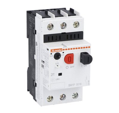
SM1P0100 Circuit Breaker
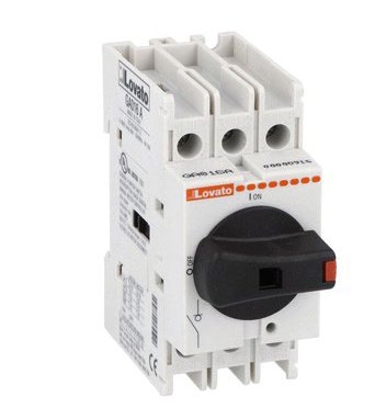
GA025A Disconnect Switch
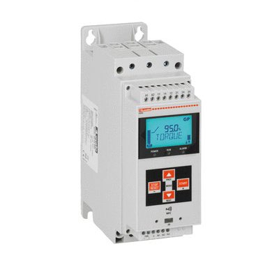
ADXL Series Soft Starter
SWITCHING-DEVICE ARCHITECTURES
There are three ways to build the switching half of the layer:
- A motorized changeover switch: A single mechanism whose motor operator drives the contacts between two positions with a mechanical interlock that makes a bothsources- closed state physically impossible.
- A pair of mechanically and electrically interlocked contactors, common in lighter-current applications and easy to integrate into a contactor-based panel.
- A pair of motorized molded-case breakers, used where the transfer point also needs overcurrent protection and higher interrupting capacity.
No matter the architecture, transfer equipment in North America is evaluated to UL 1008, which subjects the device, manual or automatic, to withstand, endurance and operational testing that a general-purpose disconnect of the same ampere rating has not passed. Substituting a switch with the right current rating but not the UL 1008 listing places an unqualified device at the most safety-critical node in the system. The overall system — switching device, controller and any auxilliary equipment — must be reviewed and submitted to achieve the UL1008 standard. We recommend pairing the controller and switching device with the same manufacturer. Engineered as a matched set, they remove the integration guesswork of mixing vendors and reduce the parts count in the transfer cabinet.
METERING AND ENERGY EFFICIENCY
The current transformers, voltage sensing, power calculation and communications quantify how efficiently the facility runs. Efficiency is tracked with Power Usage Effectiveness (PUE), which is the ratio of total facility energy to IT-equipment energy and is referenced in the ISO/IEC 30134-2 standards.
The gap between average and best practice is wide. According to Uptime Institute survey data, the industry-average PUE has sat near 1.56 for several years, even as the best hyperscale fleets operate around 1.08 to 1.12. Because cooling can reach 40% of a data center’s energy and energy can represent 30 to 50% of operating expense, every fraction of a point of PUE is energy that shows up on both the utility bill and the facility’s carbon reporting.
Closing that gap requires measurements beyond a single utility meter. Multifunction power analyzers on distribution boards capture true RMS current and voltage, active and reactive power, power factor and harmonic distortion, and they flag anomalies before they become failures. Branch-level metering pushes measurement down to individual circuits, enabling operators to see where the non-IT energy goes.
RS-485 with Modbus RTU and Ethernet with Modbus TCP carry the data into the Data Center Infrastructure Management (DCIM) or building management system as trend analysis, alarms, and automated reports. Regulation is moving the same way. Under the EU’s recast Energy Efficiency Directive, data centers began reporting energy performance, including PUE, in 2024, making efficiency a compliance and sustainability argument, instrumented at the same boards that carry the transfer and protection functions.
THE MRO OPPORTUNITY AND THE ROAD AHEAD
For distributors, integrators and service providers, the expanding maintenance, repair and operations (MRO) market is a growing opportunity to deliver reliability, efficiency and continuity. Because data centers run continuously, operators must prioritize preventive maintenance, rapid component replacement and long-term reliability planning. Energy monitoring and intelligent control let MRO teams optimize maintenance schedules, reduce emergency calls and extend the life of motors, cooling, generators and distribution equipment.
For decades, power continuity and energy efficiency were treated as separate engineering problems. In the modern data center both are monitored and controlled in the same equipment, and specifying that layer as one designed system is what keeps uptime, cost and carbon under control.